

How To Receive Characters Out Of Uart Register Pic24
USART/UART is a serial communication protocol that is used to transfer data serially. In other words, it transfers data scrap-by-chip. One of the principal advantages of this communication method is that fewer wires are required to transfer. Consequently, the speed of data transfer will be slow every bit compared to parallel communication techniques. All mid-range and advance Motion picture microcontrollers have born UART or USART modules. UART stands for a universal asynchronous receiver and transmitter. On the other paw, the USART module supports data transfer in both synchronous and asynchronous modes.
In this tutorial, we will learn how to use the USART module of the PIC18 series microcontroller. We will use a PIC18F4550. However, you can apply the aforementioned concepts to other PIC18F or PIC16F serial microcontrollers. Considering the UART control registers are exactly the same in all microchip devices.
Why nosotros need UART Communication?
As yous know that all modernistic microprocessors and microcontrollers transfer data to other digital devices in bytes. Two modes of communication are used to transfer information. I is parallel and the other one is a serial method. Parallel manner is used when high-speed transmission needed, and altitude is brusque betwixt the sender and receiver. On the contrary, Series communication is used for long-range data communication and when less number of connecting wires (GPIO pins) are available. For example, in the case of microcontrollers, full general-purpose input-output ports are usually less. Therefore, Microcontrollers employ serial communication to transmit and receive information from other devices.
UART Communication Brief Description
UART advice is of ii types such every bit synchronous and asynchronous. Asynchronous is the most widely adopted method in microcontrollers and peripherals that used to transfer information serially. In the asynchronous protocol, the 8-bit data(byte) parcel is embedded within a start and stop bit. This is also known every bit a UART information frame. Sometimes one actress parity bit is as well used before the end scrap. Parity bit checks if information changes during transmission or not.
UART Data Transmission Procedure

- Normally when no information transmission occurs, UART lines remain active high.
- When the transmitting microcontroller wants to transmit information, it makes the serial line low for one clock cycle.
- After that receiving device detects this point transition and starts to read the data frame.
- The speed of data reception depends on the baud rate.
- After that transmitting microcontroller sends a low to high betoken for at to the lowest degree two clock cycles to bespeak the end of the information frame.
For further information, read this tutorial on UART Advice Basics and Working.
Motion-picture show Microcontroller UART Module
PIC18F4550 microcontroller has one USART module. Synchronous Asynchronous Receiver Transmitter (USART) module can be configured either in Full-Duplex or half-duplex mode. In full-duplex mode, data transfer simultaneously in both ways (transmit and receive). On the contrary, in one-half-duplex style, data transfer only in one management at a time. Peripherals such as ADCs, serial EEPROM, D/A converters demand only half-duplex manner. Flick microcontrollers support both modes.
UART Pins PIC18F4550
UART pins of this motion picture microcontroller bit are bachelor on PORTC pins such equally RC6/TX and RC7/RX. That means RC6 is a transmit pin and RC7 is used to receiving data. Before using these pins for serial communication, nosotros should set management control registers of these pins to logic high.
TRISCbits.RC7 =1 // bit must exist set (= 1) TRISCbits.RC6 = 1 // flake must be ready (= 1)
Although the receiver pivot should be set every bit digital input and transmitter pin as an output. But the UART module will fix these pins input to output automatically according to requirement.
PIC18F4550 UART Module Configuration Registers
Now let's starting time with Internal configuration registers and how to utilize these annals to configure the UART advice module of PIC18F4550 microcontroller. There are three main control registers associated with the PIC18F4550 microcontroller UART module:
- Transmit Status and Control (TXSTA)
- Receive Status and Control (RCSTA)
- Baud Rate Command (BACON)
We can control the complete data receiving and transmission operation of the UART module with these 3 registers. Simply if you want to utilise UART with interrupt, we need to configure some interrupt control registers also. bUT We meet interrupt example in later part of this tutorial.
Data Registers
Other than control registers, four other registers are used for information storage, data transmission and for Baud rate generation. Like control registers, Data registers are also of 8-bit size.
- TXREG USART Transmit Register: It holds the data that the transmitter device wants to transport to a receiver device.
- RCREG EUSART Receive Register: It stores data that PIC18F4550 microcontroller on RC7 pin.
- SPBRGH and SPBRG: These 8-bit registers are used to calculate the baud rate.
UART Transmit Status and Control (TXSTA)
This is an viii-bit register that is used to control and enable transmission features. Firstly, it selects information transfer type either synchronous or asynchronous. Secondly, it chooses the information frame size ( viii-bit or 9-chip).

Bit7 CSRC – Clock Source Select Bit
This bit selects the clock source input for the UART module. PIC18F4550 supports both synchronous and asynchronous modes of communication. Asynchronous series communication does not crave a clock source. Therefore, this bit acts every bit a don't care, if you lot are using asynchronous fashion. In this tutorial, we volition be using asynchronous fashion. Therefore, information technology volition exist a don't care.
On the other hand, if the synchronous mode is selected, nosotros should configure CSRC according to the principal and slave mode.
- Ready CSRC= i, if you want to utilize Master mode and clock generated internally from the baud charge per unit generator
- Gear up CSRC= 0, if slave way selected and the clock volition exist used from an external source
Bit6 TX9 – Data width Selection
TX9 selects information format width either 9-bit transmission or eight-bit manual.
TXSTAbits.TX9=one // selects 9-flake data manual format TXSTAbits.TX9=0 // selects 8-bit data transmission format
Bit5 TXEN – Transmission Enable
It used to enable and disable transmit data from UART pivot RC6/TX.
TXSTAbits.TXEN = 1 //Transmit enabled TXSTAbits.TXEN = 0 // Transmit disabled
Bit4 SYNC (Advice Mode Select)
This bit selects the synchronous and asynchronous way. Setting SYNC to one selects synchronous and other asynchronous.
Bit3 SENDB ( Ship Break Character)
It sends a bespeak to show that transmission is completed.
Bit2 BRGH ( High Baud Rate Selector )
This is a high baud rate select flake. By default, a low-speed mode is selected. If we want to use loftier speed, then nosotros tin set BRGH =1 to become a high baud rate. By setting BRDG, we can double the baud rate with the same operating frequency of a microcontroller.
Bit1 TRMT ( Transmit Register Condition )
Information technology is a flag bit that shows the condition of transmitting shift register ( TXREG ).
- If TRMT= 0, that means data transmission is in process and TXREG still holds data.
- Otherwise, if TRMT=ane, that ways microcontroller completed information transfer and TXREG is empty.
Bit0 TX9D ( ninth Bit of Data Frame)
This is a readable bit. We tin address it either equally a 9th chip of data or a parity bit.
Movie UART RCSTA: Receive Status and Command Register
RCSTA is an 8-scrap register used to plan the UART receiver module of PIC18F4550 microcontroller. Besides other functions, it enables/ disables the UART pins to receive data on the RX pin.
- SPEN Bit7
SPEN enables/disables the UART pins of PIC184550 such as RC6/TX and RC7/RX.
RCSTAbits.SPEN = 1 // enables the serial communications pins RCSTAbits.SPEN = 0 // disables series advice port and remains in reset style.
- RX9 Bit6
Similar to TX9, information technology selects the size of the data reception ( 9-chip reception or 8-fleck reception). Just maximum microcontrollers and peripherals back up 8-fleck information reception.
RCSTAbits.RX9 = ane // ix-bit reception RCSTAbits.RX9 = 0 // 8-bit reception
- SREN Bit5
This is a Unmarried Receive Enable bit that is used in synchronous information transfer. We volition exist using asynchronous mode and this bit is used for synchronous communication only.
- CREN Bit4
CREN is a continuous receive enable bit.
RCSTAbits.CREN = ane // It enables receive register to continously receive information RCSTAbits.CREN = 0 // Otherwise disable
- ADDEN Bit3
ADDEN enables address detection in asynchronous mode when the data width is ix-bit ( RX9=1). Otherwise, if Asynchronous mode 8-bit is selected, this bit volition exist don't care.
- FERR Bit2 Framing Mistake Flake
RCSTAbits.FERR = ane // Framing error RCSTAbits.FERR = 0 // No Framing error
- OERR Bit1 Overrun Error Bit
RCSTAbits.OERR = 1 // Overrun Error RCSTAbits.OERR = 0 // No Overrun Mistake
- RX9D Bit0
RX9D is the 9th bit of received data. This ninth bit can be a parity scrap, accost and data. But if yous are using an 8-scrap information mode, set RX9D=1.
How to Calculate Baud Charge per unit of PIC8F4550 UART?
What is Baud Rate?
Baud rate defines the rate of data transfer between 2 devices such as transmitting and receiving microcontrollers. Information technology is also known as bits per second. This data transfer rate depends on the type of microcontroller or device we are using. Some old computers support the transfer rates between 100 to 9600 bps. Nonetheless, modern microprocessors and microcontrollers back up up to 56k.
This table shows some of the about widely used baud rates for PIC18 microcontrollers that are used to transfer data between the microcontroller and personal computers.
| Number | Baud charge per unit |
|---|---|
| 1 | 1200 |
| 2 | 2400 |
| 3 | 4800 |
| iv | 9600 |
| v | 19200 |
| 6 | 38400 |
| 7 | 57600 |
PIC18F4550 Microcontroller Baud Rate Registers
Only in the case of pic microcontrollers, the baud rate is programmable. For PIC18F4550 microcontroller, we can set up the desired baud rate with this formula:
Desired Baud Rate = FOSC/(64 ([SPBRGH:SPBRG] + ane))
Where:
- FOSC is an operating frequency of PIC18F4550 microcontroller
- SPBRGH: SPBRG: We should upload values of the nearest integer to these ii registers co-ordinate to the desired baud rate.
In the above formula, the SPBRGH: SPBRG registers values are only unknown. Because we know the desired data transfer rate. Therefore, we can rewrite the above formula like this :
SPBRGH: SPBRG =( FOSC / 64 x Baud_Rate ) - 1
For case, we desire to ready the baud charge per unit of 9600 and FOSC is 20MHz. Hence:
SPBRGH: SPBRG = ( 20 MHz / 64 x 9600) - ane SPBRGH: SPBRG = ( 20 MHz / 614400) - ane = 31.55=32
Hence SPBRG=0 and SPCRG=32.
Note: This adding is based on BRGH =0 of the TXSTA register. Because we didn't enable loftier-speed data transfer options. Simply if you enable BRGH =1, this formula volition go:
SPBRGH: SPBRG =( FOSC / 16 x Baud_Rate ) - 1
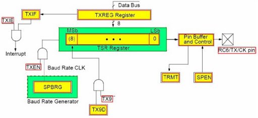
PIC18F4550 UART Programming to Send Information Serially
In this department, we will see how to send data serially using UART transmit pin of PIC18F4550 microcontroller. Follow these steps to program to send data serially:
- Outset place the data ( byte) inside a transmit annals (TXREG) of UART. We can ship a maximum of one grapheme at a time. Considering UART transmits register is of eight-bit size and UART series communication supports maximum nine-flake of a data frame.
- TXREG is a transmit shift annals whose part is to become information from the microcontroller and transport information technology to TX pivot serially scrap by scrap.
- Subsequently that enable TXEN and initialize baud rate.
- When it completes sending data serially, the TRMT flag becomes high that indicates that manual is completed.
PIC UART Transmitter Code
This example code transmits data serially to any UART based device at the baud charge per unit of 9600. Before using this code, you should include a configuration file for the PIC18F4550 microcontroller. You can generate a configuration file using the MPLAB XC8 compiler.
#include <xc.h> // Includes header file for PIC Microcontroller #include "pic18f4550_config.h" // Include configuration file #define F_CPU 8000000/64 // value to calculate baud rate // This function used to generate filibuster in miliseconds void MSdelay(unsigned int val) { unsigned int i,j; for(i=0;i<=val;i++) for(j=0;j<81;j++); } //This function initialize UART module void UART_Initial(long baud_rate) { float bps; TRISCbits.RC6=1; TRISCbits.RC7=i; bps = (( (float) (F_CPU) / (bladder) baud_rate) - ane); // sets baud rate SPBRG=(int)bps; // store value for 9600 baud rate TXSTAbits.CSRC = 0; // Don't intendance for asynchronous mode TXSTAbits.TX9 = 0; // Selects 8-bit data transmission TXSTAbits.TXEN = ane; // Enable Data tranmission on RC6 pin TXSTAbits.SYNC = 0; // Selects Asynchronous Serial Communication Fashion TXSTAbits.BRGH = 0; // Default Baud rate speed BAUDCONbits.BRG16 = 0; // selects only 8 bit register for baud rate RCSTA = 0x90; // Enables UART Communication PORT } void UART_Write( char data ) { //while (TXIF == 0); TXREG = information; while(TRMT==0); // wait until transmit register not empty } void main(void) { OSCCON=0x72; // Select internal oscillator with frequency = 8MHz UART_Initial(9600); while(i) { UART_Write('U'); // Send grapheme A UART_Write('A'); // Send character A UART_Write('R'); // Send carriage return for new line UART_Write('A'); // Ship graphic symbol A UART_Write('T'); // Send carriage return for new line UART_Write('\r'); // Send carriage return for new line MSdelay(1000); // adds delay of one 2d } render; } This code sends UART on transmit TX pin after every one 2d. For demonstration purposes, we have used a virtual terminal in proteus. The virtual concluding used emulate hyper terminal to transport and receive data serially. As yous see this simulation, terminal receives 'uart' text after every one second.
- To simulate this in proteus, copy the higher up lawmaking and generate configuration $.25 with MPLAB XC8 compiler and add together as a header file.
- After that generate Hex lawmaking, upload in proteus and click on play push button. Y'all will see this outcome in virtual terminal.
PIC18F4550 UART Programming to Receive Data Serially
In this department, we will meet how to receive information on the UART pin (RC7/RX) of the PIC18F4550 microcontroller. The code for the receiver role is almost the aforementioned as the transmitter office look this UART_READ() role.
char USART_Read() { while(RCIF==0); // see if data on RC7 pin is available if(RCSTAbits.OERR) { CREN = 0; NOP(); CREN=1; } return(RCREG); //read the byte from recieve register and return value } This line first checks if data is available to read. If not, it will keep waiting and hold there.
while(RCIF==0); // see if data on RC7 pin is bachelor
If available, OERR checks, if there is whatever overrun mistake in the data. Later on that, information technology receives information from RCREG and returns through a role phone call.
Flick UART Data Receiving Plan
In this example lawmaking, we volition turn on LED based on the data received on serial receive pin of PIC18F4550 microcontroller.
#include <ninety.h> #include <stdio.h> #include <string.h> #include <stdlib.h> #include "pic18f4550_config.h" // Include configuration file #define F_CPU 8000000/64 // value to calculate baud rate void MSdelay(unsigned int val) { unsigned int i,j; for(i=0;i<=val;i++) for(j=0;j<81;j++); } void UART_Initial(long baud_rate) { float bps; TRISCbits.RC6=1; TRISCbits.RC7=i; bps = (( (float) (F_CPU) / (float) baud_rate) - 1); // sets baud charge per unit SPBRG=(int)bps; // store value for 9600 baud rate TXSTAbits.CSRC = 0; // Don't care for asynchronous mode TXSTAbits.TX9 = 0; // Selects 8-fleck data manual TXSTAbits.TXEN = 1; // Enable Data tranmission on RC6 pin TXSTAbits.SYNC = 0; // Selects Asynchronous Series Advice Mode TXSTAbits.BRGH = 0; // Default Baud charge per unit speed BAUDCONbits.BRG16 = 0; // selects only eight bit register for baud rate RCSTA = 0x90; // Enables UART Communication PORT } char USART_Read() { while(RCIF==0); // encounter if information on RC7 pin is available if(RCSTAbits.OERR) { CREN = 0; NOP(); CREN=1; } render(RCREG); //read the byte from recieve register and render value } void main(void) { char data; OSCCON=0x72; // Select internal oscillator with frequency = 8MHz TRISDbits.RD0=0; //Make RD0 pivot as a output pin PORTDbits.RD0=0; //initialize RD0 pin to logic zeeo UART_Initial(9600); while(1) { data=USART_Read(); if(data=='A') PORTDbits.RD0=1; else PORTDbits.RD0=0; } return; } We connect an LED with an RD0 pin of PORTD. We define this pin as a digital output pin. If information received on the RC7/RX pivot is character 'A', LED will plow on. Otherwise LED remains off whatever information receives serially.
You tin can read this tutorial on How to utilise GPIO pins of Flick Microcontrollers if you don't know how to interface a Light-emitting diode with a pic microcontroller.
Lawmaking Working
In this code, the only new part is the data receiving and LED controlling part. The rest of the code is same. I have already explained UART_Read office above.
data=USART_Read(); if(data=='A') PORTDbits.RD0=1; else PORTDbits.RD0=0;
- In this code, this line 'data=USART_Read();' receives data and store information technology inside a grapheme type variable 'data'.
- If condition checks if received character is equal to A.
- After evaluating this status, if the answer is truthful, the RD0 pivot will go high and turns on the LED.
- Otherwise LED will remain off.
Summary
In this tutorial, we take learned the following concepts of PIC Microcontroller UART:
- Command and Data Registers Configuration
- How to send a string with picture UART
- How to utilize receive cord with pic UART
We used a polling method to transmit and receive data. But we can utilize interrupt routine also. To explore farther check this advance tutorial:
- Employ UART Interrupt of Pic Microcontroller with Examples
- How to employ DAC Module of Pic Microcontroller and Generate waveforms
- PIC Microcontroller ADC – How to Use PIC18F4550 ADC

How To Receive Characters Out Of Uart Register Pic24,
Source: https://microcontrollerslab.com/uart-communication-pic-microcontroller-mplab-xc8/
Posted by: sussmanciary1980.blogspot.com
0 Response to "How To Receive Characters Out Of Uart Register Pic24"
Post a Comment